
The STMISOLA connects to
- AMI100D, HLT100C or UIM100C (interface model associated with the MP1X0 system) Analog Output 0 or 1 port
- STM100C 50 Ω output port
- OUT5 interface for MP36 or MP36R analog output signal drive ±10 V input
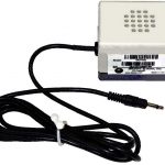
The STMISOLA ships with cables to allow additional connections
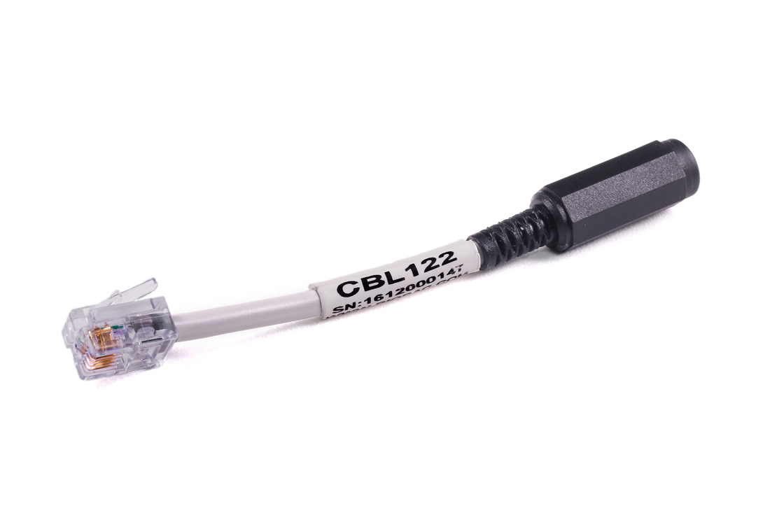
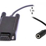
- Includes two unisolated cable adapters (2 x CBL122 male RJ11 to 3.5 mm female jack); the short (~3 cm) adapter is designed to be connected to another cable. The first adapter allows a mono 3.5 mm male cable to be interfaced with the AMI100D/HLT100C, the second can be used with the 3.5 mm Y-splitter to allow the stimulator control signal to be recorded on another channel and looped back into the AMI100D/HLT100C.
- This cable adapter is unisolated and must not be used with external equipment when a human subject is connected to the MP system unless the external equipment has its own built-in isolation.
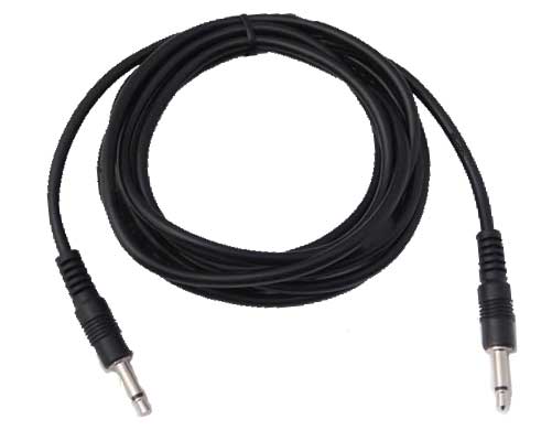
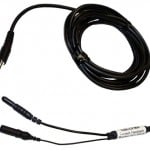
- Includes 3.5 mm to 3.5 mm cable (CBL100) for connection to Digital I/O on the UIM100C rear panel.
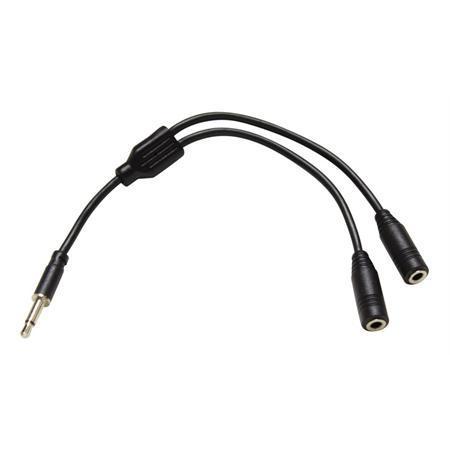
- Includes Y-Splitter (CBL212) to permit the MP160/150 to sample the drive waveform from stimulus presentation setups; permits recording of the drive waveform timing and amplitude.
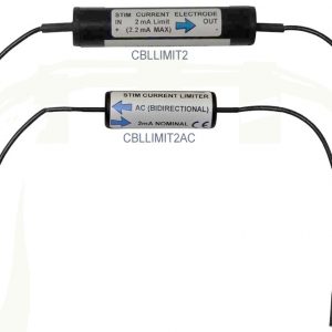
The Current Feedback Monitor Cable (CBLCFMA) is recommended for use with any voltage stimulator; to isolate CBLCFMA output, use INISO and AMI100D/HLT100C. Always make sure to place the electrodes on the participant at least 10 minutes before starting any electrical stimulation. Use a CBLCFMA to monitor and record the actual current delivered to the participant at ALL times. A large enough change in current delivered to the participant will alter the subjective perception of the stimulation. Thus, an unpleasant shock may become painful if more current starts being delivered or become ineffectual if less current is being delivered than during threshold identification. Changes in the levels of delivered current are due to changes in impedance. Changes in impedance could be due to a number of factors: gel saturating the skin over time; gel drying up—over longer period of times; hydration level of participant; sweating; decoupling of electrodes and skin due to motion artifacts; etc.
Voltage (V) mode—the STMISOLA multiplies the Control Input Voltage by a factor of 20, to present that amplified signal at the STMISOLA output.
In the case of a maximum ±10 V Control Input Voltage, the STMISOLA will output a ±200 V signal, with an output impedance of either 100 ohms or 1 K ohms. These output impedance settings will act to limit the available output current.
Current (I) mode—two settings:
The STMISOLA provides two options for output current mode.
-
- High current mode (Zout switch set to 100 ohms), provides a gain factor of 10 ma/volt.
- Low current mode (Zout switch set to 1 K ohms), provides a gain factor of 1 ma/volt.
The STMISOLA multiplies the Control Voltage by the factor indicated (K in ma/V) to present that associated output current at the STMISOLA output.
In the case of a maximum ±10 V Control Input Voltage, for:
Zout = 100 ohms, K=10 ma/V: the STMISOLA will output ±100 ma
Zout = 100 ohms, K=1 ma/V: the STMISOLA will output ±10 ma
In both cases, the voltage compliance is ±200 V.
Rise Time Measurement Setup
Load: 1 kΩ
Input Control Signal: 0-1 Volt square wave (1 µsec rise time or less)
Current Monitor: CBLCFMA Current Monitor (in series with stimulus output current)
Rise times (10%-90% stimulus output current amplitude levels indicate rise time)
- Voltage mode (Zout = 100 Ω or 1 kΩ): 10 µsec nominal
- Current mode (Zout = 100 Ω – 15 µsec nominal, Zout =1 kΩ – 10 µsec nominal)
Transcranial Direct Current Stimulation
For transcranial direct current stimulation (tDCS), the STMISOLA will support arbitrarily long, constant, non-varying, direct output currents, so long as the associated voltage compliance is 100 VDC or less. The tDCS level is adjusted by holding a stable voltage to the control voltage input of the STMISOLA. The control voltage can be set in AcqKnowledge, to be output to STMISOLA via MP150 analog output. tDCS neuro-stimulation typically employs the use of low level (typically under 2 ma) constant, unipolar, direct current.
Isolation Characteristics
The STMISOLA isolates the Control Input Voltage signal from the stimulus output to 1500 VDC HiPot and approximately 1000 pF of coupling capacitance.
This very high degree of input/output isolation helps ensure subject safety and helps considerably to substantially reduce, or eliminate, stimulus artifact.
Stimulus artifact results when some percentage of electrical current from the stimulation site is directed to the recording site due to electrical leakage paths intrinsic to the stimulation/recording equipment. In the case of the STMISOLA, the leakage conductance and capacitance that permit this artifact to occur are reduced to very small values.
Power ON Safety
When you Power ON the STMISOLA, you must also hold Reset for at least 3 seconds. This forces the unit into an “operational but no output state” and protects the subject if accidentally connected to electrodes on power up.
| IMPORTANT Comprehensive Safety Guidelines for Performing Electrical Stimulation on Subjects: read Application Note 257 – Safe Use of Electrical Stimulators |
Additional Notes Regarding Use of Current Mode Output
Current Mode stimulus output can appear to demonstrate non-intuitive behavior. This behavior is very different than Voltage Mode stimulus output. The STMISOLA is a voltage-controlled stimulation system. In the case of Current Mode output, options exist to map the stimulus output current to the input control voltage. These two options are:
Option 1) +10 V input control voltage maps to +100 ma stimulus output current and -10 V input control voltage maps to -100 ma stimulus output current
Option 2) +10 V input control voltage maps to +10 ma stimulus output current and -10 V input control voltage maps to -10 ma stimulus output current
The behavior is essentially the same for both Option 1) and Option 2), even though the stimulus output current range is different. When the input control voltage is close to 0 V, then the stimulus output current is also proportionally close to 0 ma.
IMPORTANT NOTE
When attempting to set the input control voltage to zero volts, the resulting voltage will most certainly never be exactly zero volts. Instead of zero, the input voltage will simply be close to zero, perhaps on the order of +0.001 V or -0.00001 V. So, if the input control voltage is non-zero, then the current output will also be non-zero!
Example A:
A non-zero input control voltage of 0.001 V will result in a non-zero stimulus output current of 0.001 ma, assuming STMISOLA is set to Option 2). If the STMISOLA stimulus output is connected to an infinite (or very large) impedance, then the STMISOLA will attempt to drive 0.001 ma through this very large impedance. Assuming the large impedance is 200 Mohm, then:
0.001 ma x 200,000,000 ohms = 200 V (estimate)
Accordingly, in practical operation, if the STMISOLA is used in current mode and is attached to electrodes that are making intermittent contact to the tissue of the subject, then intermittent shocks may be felt by subject, even if 0 V is applied to the input control voltage. This is because the STMISOLA will drive directly to the compliance voltage limit and then start to behave as a voltage stimulator. Intermittent contact with electrodes will result in intermittent ±200 V shocks being applied to the subject. These possible transient shocks may be felt, but only when skin electrodes dislodge and then reconnect to the subject tissue.
This possible ±200 V stimulus will be present on STMISOLA output leads at the point when the electrodes reconnect with the tissue, assuming the electrodes had dislodged previously. At the point of reconnect, the voltage level falls back below the compliance threshold and the errant stimulus goes away, but this process takes a few microseconds. If transient connects, and reconnects, happen over a period of time, then many bursts of voltage will impact the electrode sites.
Methods to mitigate this potential safety issue include:
- Employ a bipolar voltage clamp across the stimulus output current leads.
- Employ an added parallel resistance across the stimulus output current leads.
- Use both methods together, for additional safety consideration.
In method 1), the bipolar voltage clamp simply limits the compliance voltage to a deemed safe level. Two, oppositely directed, diode and Zener diode series circuits are used to define the voltage clamp maximum value, assuming the stimulus electrodes may become dislodged.
In method 2) the maximum load impedance will be dictated by the chosen added parallel resistance.
Example B:
Using the Example A, also assume that a parallel resistance of 1 Mohm is employed across the stimulus output current leads. Accordingly, the reference equation becomes:
0.001 ma x 1,000,000 ohms = 1 V (estimate)
In this case, the maximum stimulus voltage received by the subject, in the event of sporadic electrode contact, would be on the order of 1 V, instead of 200 V. Alternatively, if the parallel loading represented by the additional 1 Mohm resistance is not desired, then a voltage clamp could be used to limit the maximum output voltage level in the event of sporadic electrode contact.
The STMISOLA has the capability of acting as a nearly ideal current stimulator, with very high performance. Adding a parallel resistance or a voltage clamp reduces performance from ideal, but enhances safety. Please contact BIOPAC Systems for more information.
Stay Connected