
The threshold for the OUT102 is determined by adjusting the amplitude control on the STM100C module; the OUT102 Piezo transducer may be connected directly to the STM100C stimulator module 50 ohm output. When the STM100C stimulator module output rises above 1.5 volts, the OUT102 piezo indicator will emit a constant audible signal (3.0 kHz @ 80dB).
- Accordingly, the device is very useful for providing an audible stimulus, or alarm, when a physiological signal passes a certain threshold. As such, the OUT102 makes an excellent audible BPM indicator for ECG, blood pressure or respiration signals.
- The specific Biopotential or Transducer amplifier signal monitored can be recorded while simultaneously directed through the STM100C module.
The device can also be used to indicate when temperature or other slowly moving variable (e.g., electrodermal response) passes a certain threshold.
- To operate as described here, the source amplifier needs to be set to CH16, STM100C is set to CH16 input, and source signal must be able to reach at least +1.5 V of amplitude. Source signal gain can typically be sufficiently adjusted by using the gain switch on the source amplifier module. STM100C amplitude control can be used to attenuate the source signal, as required, to help activate the Piezo transducer on only the desired source signal portions.
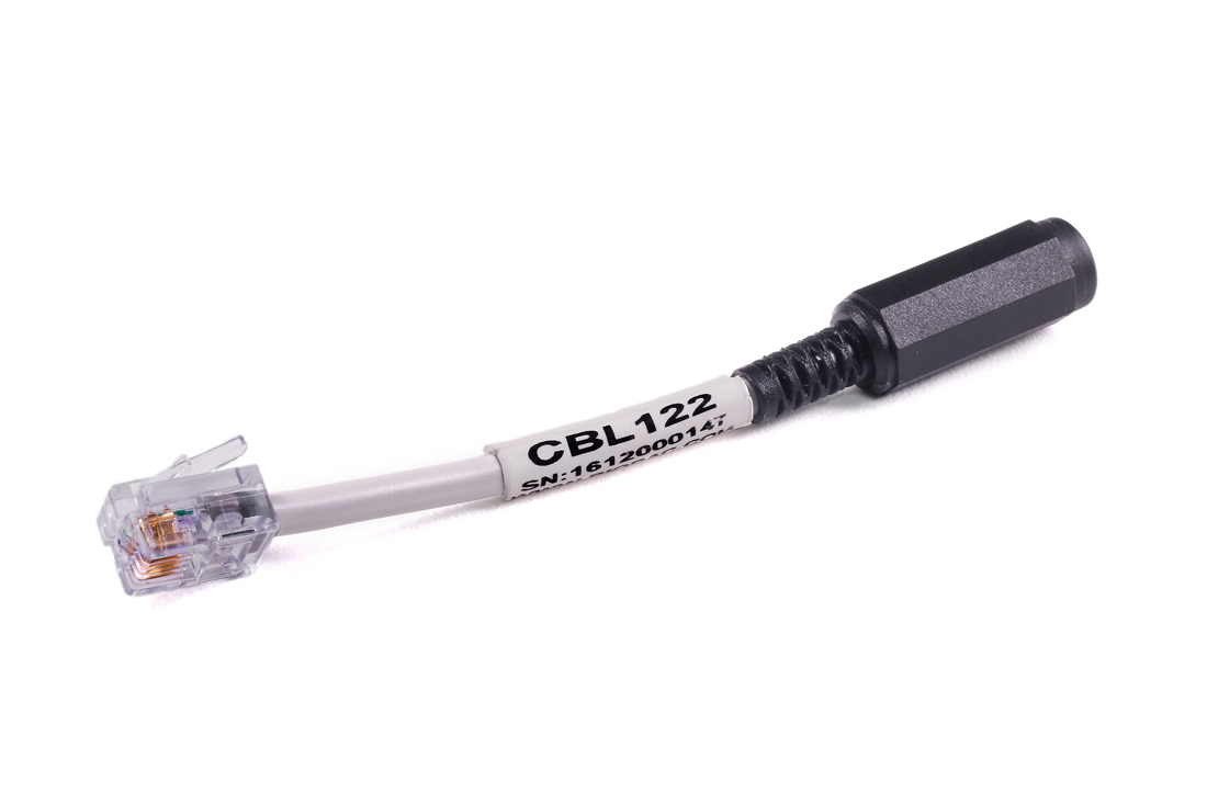
The OUT102 also connects directly to the UIM100C digital I/O ports for operation with Control Channel outputs. An adapter is included for connecting the OUT102 to the UIM100C digital I/O ports. With this setup, during acquisition, the stimulus level and timing will be indicated on the recording.
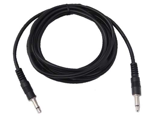
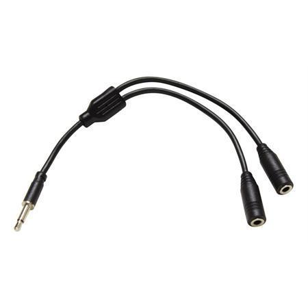
- The included splitter (CBL212 3.5 mm male mono phone plug to two 3.5 mm female mono sockets) and connector cable (CBL100 3.5 mm mono male to 3.5 mm mono male) permit the analog drive signal to be directed to two locations. The drive signal—usually from DA0 or DA1—is typically directed to the splitter cable. One socket output of the CBL212 splitter cable is directed to the OUT102 input. The other socket output of the CBL212 splitter cable is looped back to drive an available MP input, via CBL100, through the UIM100C.
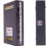
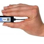
The OUT102 case is (W x L x H) 50.29 mm x 65.41 mm x 45.15 mm with a 1.8 m cable terminated in a 3.5 mm phone plug.

Stay Connected