
Key features
- 16 Digital +5 V TTL Lines
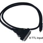
- 8 TTL Input
- 8 TTL Output
- TTL Input Lines configured as an 8 bit port
- TTL Output Lines configured as an 8 bit port
- Change detection on TTL Input lines
- TTL Input to 2 hex bytes conversion representing 255 possible states
- Event marking: 2 hex bytes to TTL Output across 8 bit port representing 255 possible states
- TTL Output lines automatically latch once set
- Works out of the box with PCs/Macs/Linux—fully plug in & play
- Appears as a Virtual Com Port (VCP)
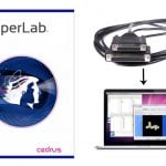
- Compatible with all Psychology experiment generators, e.g., E-Prime, SuperLab, Presentation, Inquisit, DMDX, ERTS, DirectRT, PsyScope, PsychoPy, OpenSesame, etc.
- Works with any software that can access a standard serial port
- Comes complete with timing validation software which checks round trip timing on your PC
- Fully documented API complete with examples
- Small and unobtrusive—Dimensions (WxHxD): 67.1 mm x 28.2 mm x 67.1 mm
- LED indicators for Input (green) and Output (red)
- Full-speed USB 2.0 (compatible with USB 3.0)
- Scans for TTL I/O changes 109,000 times each second
- Millisecond accurate TTL event marking*
*Accuracy may be limited by PC and experiment generation software selected for stimulus presentation.
Utilizes The Black Box ToolKit technology.
Hardware Connections

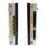
Figure 1: Back of MP36 showing location of I/O Port |
MP36, MP36, MP35R
Digital signals may be brought in and out of MP36 (or older MP35) or MP36R through the I/O Port on the back of the device. To interface a parallel port or emulator, an STP35B (or older STP35A) must be connected to the I/O Port. IMPORTANT! These are NOT equivalent to straight-through cables. An off-the-shelf DB25 cable will not make the proper connections. |

Figure 2: MP46 and BN-SMART-IOCBL |
MP46 or Smart Center
MP46 and Smart Center can connect to a parallel port or emulator through BN-SMART-IOCBL. The connection between BN-SMART-IOCBL and parallel port may be through a CBL110C or any other straight-through cable with appropriately gendered DB-25 connectors at the ends. |

Figure 3: Location of printer port on Isolated Digital Interface (shown on STP100C-C with MP150, same on STP100D-C with MP160) |
MP160 or MP150
Digital signals may be brought into an MP160 (or older MP150) System via an STP100D-C isolated digital interface module (or older STP100C-C).
|

Stay Connected