![]() For MRI applications, when considering the possible use of the STM200 for associated electrical stimulation of human subjects, please refer to BIOPAC Application Note 257 | Safe Use of Electrical Stimulators for context, warnings and details.
For MRI applications, when considering the possible use of the STM200 for associated electrical stimulation of human subjects, please refer to BIOPAC Application Note 257 | Safe Use of Electrical Stimulators for context, warnings and details.
The Current Feedback Monitor Cable (CBLCFMA) is recommended for use with any voltage stimulator; to isolate CBLCFMA output, use INISO and HLT100C. Always make sure to place the electrodes on the participant at least 10 minutes before starting any electrical stimulation. Use a CBLCFMA to monitor and record the actual current delivered to the participant at ALL times. A large enough change in current delivered to the participant will alter the subjective perception of the stimulation. Thus, an unpleasant shock may become painful if more current starts being delivered or become ineffectual if less current is being delivered than during threshold identification. Changes in the levels of delivered current are due to changes in impedance. Changes in impedance could be due to a number of factors: gel saturating the skin over time; gel drying up – over longer period of times; hydration level of participant; sweating; decoupling of electrodes and skin due to motion artifacts; etc.
| IMPORTANT Comprehensive Safety Guidelines for Performing Electrical Stimulation on Subjects: read Application Note 257 – Safe Use of Electrical Stimulators |
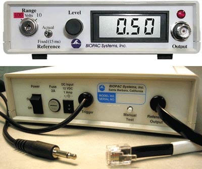
Controls & Connections
Front Panel
Range
Establishes the stimulus pulse output level range in Volts (.025-10 Volts or .12-100 Volts).
- Turn right to select a range up to 10 Volts.
- Turn left to select a range up to 100 Volts.
- Remove the key for added safety and control.
If the Range is changed before recording begins, the scaling must also be changed (MP menu > Set Up Channels) to maintain direct Level recordings.
If the Range is changed during recording, the user should manually enter a software marker to note the change (F9 on Windows or Esc on Mac). The pulse Level could then be determined by (mentally) moving the decimal place to the right or left, depending on how the Range was changed.
Refers to the pulse width of the signal on the Reference Output (on the back panel).
- Actual reflects the actual output width.
- Fixed (15 ms) establishes a pulse width of 15 ms, regardless of the actual pulse width.
The Reference control only affects the pulse width; in either case, the pulse level reflects the actual output level.
Level is used in conjunction with Range to set the stimulus pulse output level. Turn the Level control (right to increase, left to decrease) to establish the desired Level, as indicated on the digital display.
Standard BNC connector to output the stimulus pulse to external electrodes or other devices.
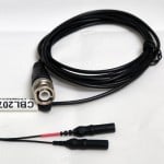
For Touchproof electrodes, add CBL207: BNC (m) to 2 x 1.5 mm TP (m)
LCD light
The red LCD is activated when the DC adapter is plugged in and the power switch on the back panel is turned ON, and flashes when the stimulus pulse is active.
Back Panel
Rocker switch for turning the STM200 power ON and OFF.
If the fuse blows and must be replaced, use a screwdriver to open (counterclockwise) and close (clockwise) the fuse cap.
Socket for DC adapter (AC300A or equivalent).
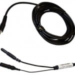
This cable terminates in a 3.5 mm mono plug for connection to the UIM100C Analog Output 0 or the STM100C 50Ω output.
Used to diagnose problems with the STM200 stimulator unit. Disconnect the “Trigger” cable from the MP System and press the Manual Test button to initiate a stimulus with a fixed pulse width of 1 millisecond.
This output cable terminates in an RJ-11 plug for connection to the HLT100C. The cable reports the stimulator marker pulse to the MP System, via the channel it is connected to. A marker pulse will be generated each time the stimulator generates a pulse. The front panel Reference switch determines the marker amplitude:


Stay Connected