

MRI Use: Conditional to 7T
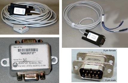
Condition: STM100C Stimulator stays in the Control Room and is used with the MECMRI-STMISO MRI cable set and recommended MR leads/electrodes/transducers; tested to 7T.
This MRI system is similar to the standard STMEPM but adds requisite elements to make it fully functional for stimulation requirements in fMRI and MRI.
STMEPM-MRI is not subject to the same possible errant stimulation issues as the standard STMEPM might be if suitable patch panel filtering is not constructed. STMEPM-MRI setup is restricted in terms of pulse width (2 ms max) and only voltage controlled voltage stimulation is possible; stimulation of differing intensity can be generated under E-Prime control.
For implementation of subject electrical stimulation in the fMRI and MRI for the purposes of psychophysiological research, see Application Note 282.
IMPORTANT! Read Safe Use of Electrical Stimulators – Application Note 257 for Comprehensive Safety Guidelines for Performing Electrical Stimulation on Subjects
The sample E-Prime experiment provides the necessary interface commands to communicate with the D/A unit. The D/A unit provides the STM100C with the appropriate voltage levels to stimulate a subject. The system supports up to four STM100C (and includes one).
Connections
Standalone
CBL100 connects CBLEPM to CBL122, and other end of CBL122 connects to ANALOG OUTPUT 0 of IPS100D with STM100C SOURCE set to OUT0.
Adding to existing MP System
one CBL100 connects CBLEPM to INISOA, and other end of INISOA connects to CHANNEL INPUT 16 of AMI100D and STM100C SOURCE is set to “A16” (or “CH 15” on older STM100C). CBLCFMA is connected to negative high voltage output of STMISOC, MECMRI-4, and INISOA. INISOA can be connected to any unused channel of MP system via AMI100D.
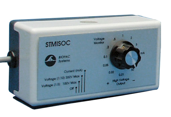
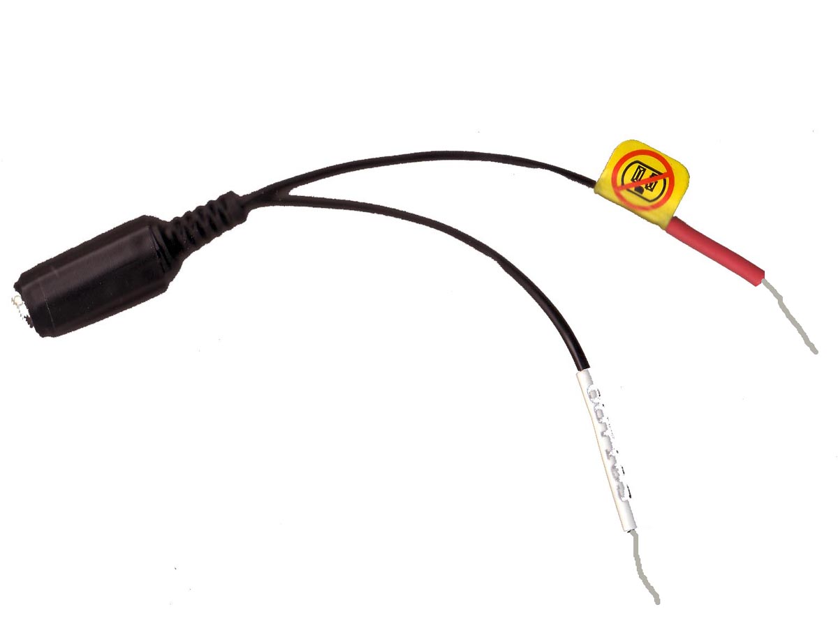
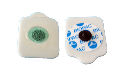
The included Current Feedback Monitor Cable (CBLCFMA) is recommended for use with any voltage stimulator; to isolate CBLCFMA output, use INISO and HLT100C. Always make sure to place the electrodes on the participant at least 10 minutes before starting any electrical stimulation. Use a CBLCFMA to monitor and record the actual current delivered to the participant at ALL times. A large enough change in current delivered to the participant will alter the subjective perception of the stimulation. Thus, an unpleasant shock may become painful if more current starts being delivered or become ineffectual if less current is being delivered than during threshold identification. Changes in the levels of delivered current are due to changes in impedance. Changes in impedance could be due to a number of factors: gel saturating the skin over time; gel drying up – over longer period of times; hydration level of participant; sweating; decoupling of electrodes and skin due to motion artifacts; etc.
Stay Connected