
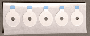
The sensors of the visual stimulus interface can be attached to the monitor using ADD208 adhesive disks or similar collars.
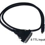
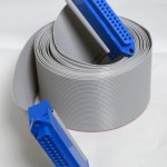
There is 1 meter of wire between the DB connector and each individual photodetector. If more length is needed to reach the STP100C or BN-SMART-IOCBL, a CBL110C DB25 female to male extension ribbon cable may be used.Pin connectors:
- Pins 2-5 of the connector correspond to the four output signals from the photodetectors.
- For a Smart Center, this corresponds to digital channels 1-4.
- For an STP100C+MP160/MP150, this corresponds to digital channels 0-3.
- Pin 21 corresponds to ground (GND).
- Pin 15 corresponds to +5 V power.
The MP36 and MP36R are not compatible with the visual stimulus interface.
Part #: STMSYNC-VIS
Stay Connected