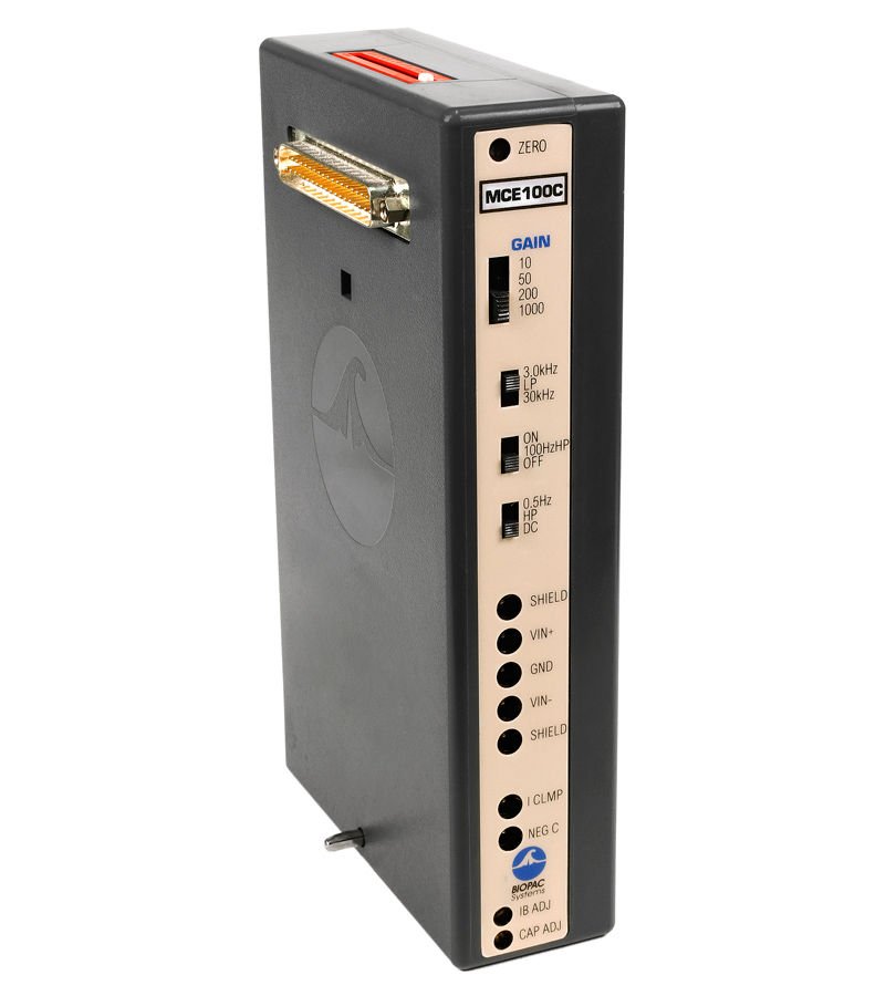
Generally considered, best performance is obtained when the mini or micro-electrode recording is performed in a shielded environment. The smaller the contact area of electrode, the higher the requirement for shielding. The MCE100C provides options for driven (voltage following) or grounded shields. Voltage following shields are useful for minimizing electrode lead input capacitance, to extend frequency response, when shielded cables are used. Grounded shields are useful for minimizing feedback noise and employed when distant shielding is utilized (Faraday cage or spiral shielding).
For special recording cases, as included options, the MCE100C provides manual controls for input capacity compensation (0-100 pF) and clamp (I-bias) current zeroing (±100 nA). In addition, the MCE100C incorporates an external voltage control to vary the clamp current proportionally to the control voltage (100 mV/nA), if required.
When performing voltage measurements using Ion Selective Microelectrodes, the adjacent shield output, associated with either the Vin+ or Vin- input, is the buffered output of the input signal (1x gain) at the Vin+ or Vin- port. These shield outputs can be used to measure reference electrode voltages (against a remote non-polarizable Ag/AgCl -indifferent- electrode) and the output of the MCE100C can be used to measure the differential voltages between a pair of ISM electrodes, one of them being the reference.
For very accurate (less than ±10 mV error) reference or differential voltage measurements, it’s important to first calibrate out amplifier offset voltages by shorting the various inputs together to obtain a true 0 volt input for each measurement type.
An MP150 D/A output channel can drive this external voltage control to change clamp currents automatically during recording. The MCE100C also includes a clamp current monitor output so the clamp current can easily be recorded by another MP150 input channel.
- The MCE100C will function with an MP100 System, but an MP150 System is recommended due to the module’s wide operational bandwidth; contact BIOPAC for details.
For general-purpose recording, without input capacity compensation or a current clamp, use standard shielded or unshielded electrode leads terminating in Touchproof sockets. Add simple input capacity compensation and current clamp control by connecting the respective signal ports to the [Vin+] input of the MCE100C using the JUMP100C jumper connectors. For the best performance and shielding, use the MCEKITC to interface your micro-electrode lead cable to the MCE100C.
Current Clamping can be enabled/disabled, by connecting/disconnecting the “I CLMP” port to either differential input of the MCE100C. Negative Capacity Compensation can be enabled/disabled, by connecting/disconnecting the “NEG C” port to either differential input of the MCE100C.
- See application Note 190 – Micro-Electrode Amplifier Guidelines – MCE100C for details.
Product Family
Product Type
MODULAR CONSTRUCTION
Amplifiers snap together for easy system configuration and re-configuration.
Intuitive, Elegant AcqKnowledge Software
Powerful automated analysis. Instantly & easily view, measure, analyze, transform, and report data.


Stay Connected