
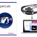
This allows you to jump to specific points in either the video or data file, and the corresponding data or video will jump to the correct time point. If you use a visual presentation system such as SuperLab, you can jump to the event markers in the data file and view the corresponding video.
AcqKnowledge 4. 1-4.2 for Windows Setup
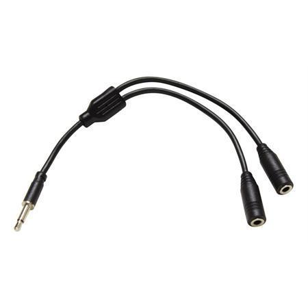
MP150/MP100 and UIM100C setupa. Connect the OUT103 2 mm pin adapter to the 3.5 mm plug on the OUT103 cable.
b. Connect the red OUT103 2 mm pin to a Digital I/O channel on the rear of the UIM100C and the black pin to GND D on the rear of the UIM100C.
c. Use MP150 > Set Up Channels to acquire and plot the Digital I/O channel the OUT103 is connected to.
d. Set MP150 > Show Manual Control– set for ‘Output’– enable the ‘Set immediately’ option– click the Digital I/O channel the OUT103 was connect to to toggle between 0 to 1If necessary, click the ‘Set’ button to update the manual control and output a digital pulse.MP36R setup – additional items requireda. Connect an OUT3 (BNC adapter) to the ‘Analog Out’ port on the rear of the MP36R.b. Connect a BSLCBL6 (interface cable: BNC to 3.5 mm) to the OUT3.c. Connect the OUT103 3.5 mm plug to the BSLCBL6 3.5 mm socket.
c. Set MP36 > Output Control ‘Low Voltage Stim’ option
– set Pulse width to 100 msec
– set Pulse level to 5 Volts– set Reference Channel to any digital channel– click the ‘ON’ button to output a digital pulse
AcqKnowledge 3.8.2-3.9.1 for Windows Setup
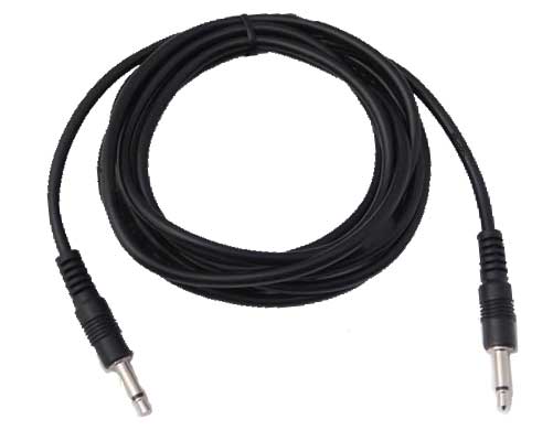
Use the OUT103 LED cable to synchronize the video camera to the MP System. Use the stimulator to turn on the LED when the MP system starts recording data. Make sure that the video camera is recording and place the LED somewhere in view of the camera so that when you start recording you will see the LED turn on. When you review the video, you will see the LED turn on and that marks the start of the data acquisition. Use the timing tools in AcqKnowledge to synchronize the video and data file.
Stay Connected