Part #: OXY-MRI-SENSOR

SPO2 Sensor for MRI
Extend Discovery into the MRI
Advanced technology for MRI-based research
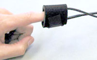 Use this pulse oximetry finger sensor (SpO2 sensor for adult human finger with two self-adhering wraps, 9 m sensor cable, and DB9 connector) with the OXY-MRI SpO2 System (one sensor is included with the system).
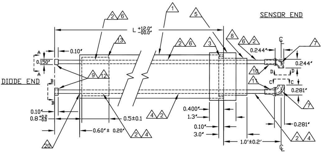
The sensor cable material is a light conducting glass bundle made up of premium achromatic glass. There is no conductive cable running through the sensor cable except what is encased in the control unit side DB9 connector. The photo detector and LED are in that end and connected to the respective fiber optic ends.
Important! Do not operate this device with the oximeter control unit or oximeter sensor connector within the MR Chamber Room. The oximeter control unit and oximeter sensor cable DB9 connector should always be positioned in the MRI Control Room with the fiber optic cable and sensor entering the MRI Chamber Room through an available waveguide.
- Place oximeter control unit and oximeter sensor cable in the MRI Control Room, then feed the oximeter sensor cable from the MRI Control Room to the MRI Chamber Room through an available waveguide. Only introduce the oximeter sensor cable and integral SpO2 finger sensor into the MRI Chamber Room.
MRI Use: Conditional
Condition: Must use MR finger sensor and must route sensor and cable through wave guide; rated to 3.0 Tesla. (See Specifications for components.)
Details
Support
Downloads/Resources
Knowledge Base
- * CLEANING GUIDELINES *
- About License Keys
- AC mode
- AcqKnowledge accuracy
- AcqKnowledge iLok key lost or unavailable
- Amplifier analog output signals
- Amplifier filter settings
- Arbitrary waveform stimulation
- Band-pass and band-stop filters
- BioNomadix Signal Interruption
- Calculating file sizes
- Calibration values
- Checking Finger Cuff Lifetime for NIBP100D/NIBP100D-HD
- Common mistakes/general troubleshooting
- Connecting Calibration Gas Tanks & Mixing Chambers
- Editing noisy data
- Electrodermal activity measurements
- Event Markers | Correcting Automated Placement
- Excel files exported from BIOPAC software open in Excel 'Protected View'
- Glossary of specification terminology
- Grounding guidelines
- High pass filters
- How can I move QRS peak event marks from the bottom of S waves to the top of R waves?
- Installation CD/DVD lost or damaged...how can I re-install software?
- Interfacing third-party transducers
- Low pass filters
- Notch filter
- Railing signal (flatline)
- Recording good data
- Troubleshooting MP160 Ethernet Communication
- Using other software with BIOPAC hardware
- VREF, reference excitation voltage
Stay Connected