Digital Trigger Unit for MRI Gating

Extend Discovery into the MRI

MRI Gating System

Digital Trigger Unit for MRI Gating
Part #: DTU100

Use the DTU100 Digital Trigger Unit to trigger an MRI system with the occurrence of the R-wave present in human or animal (high frequency) ECG or respiratory data for gating purposes. This external hardware module can accept data from any analog output associated with an MP system and convert that analog signal into a TTL compatible trigger suitable for synchronizing with external devices. The provides high-level (3,000 V) isolation between the MP System and external equipment; this isolation is very important to maintain both subject safety and high-quality signal recording. The DTU100 is always used with an AMI100D or HLT100C interface module.

See More...

Are You Looking for These?

Part #: DTU100

Details


  • For dual channel gating units see: DTU200 (small animal) or DTU300 (human)
 For the DTU100, “analog output” means:
  1. Analog output associated with any MP module (DA100C, ECG100C, etc.) that is sending data to an MP System on analog input channels 1-16.
  2. Analog output coming from the MP system via one of its D/A converters on analog output channel 0 or 1.
Interface Module
The DTU100 is always used with an AMI100D or HLT100C module. Use the RJ-11 straight through cable provided by BIOPAC to plug the DTU100 into the “Analog Output” port on an AMI100D/HLT100C (additonal cables are required for feedback views).
Feedback Views
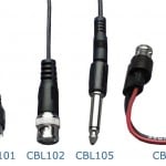
The DTU100 incorporates three feedback outputs that can be monitored on the MP System to properly set the threshold (trigger) level and required Trigger Out polarity for any type of analog input. Use cables CBL100+CBL122 to connect each respective line to an unused MP System input channel:
  • Threshold View—shows the Threshold (Trigger) Level
  • Trigger View—shows the Trigger Output as sent to the external equipment.
  • Signal View—shows the analog input signal as sent to the DTU100.

Trigger Out
Connect a TTL line with BNC female connector between the DTU100 and your trigger device.

Normal/Auto Level
The DTU100 incorporates an optional Automatic Level control circuit. The Automatic Level control circuit will expand or compress the analog input signal to fit inside of a ±5 V range.

  • If the analog input signal is clearly defined, run the DTU100 in Normal mode.
  • If the analog input signal has a widely varying baseline or significant change in amplitude from one desired trigger point to the next, consider operating the DTU100 in Auto Level mode, or try to improve signal definition.

Trigger
The Trigger LED (green) will light up whenever the Trigger Out signal goes high.

Positive/Negative
If analog data is above the threshold setting, the DTU100 output can be set to either high (+5 V) or low (0.0 V). When analog data drops below the threshold value, the output will be the opposite level.

Trigger Level
Select a trigger level (or threshold) that will fire when analog data reaches that threshold.

High-level output transducers and adapters connect to the AMI100D/HLT100C via standard 6 pin RJ11 type connectors. Transducers and adapters that presently require the AMI100D/HLT100C module are:

  • TSD109C3/J1 Tri-axial Accelerometers
  • TSD111A Heel/Toe Strike Transducer
  • TSD115 Variable Assessment Transducer
  • TSD150A/B Active Electrodes
  • INISO Adapter – Input Signal Isolator
  • OUTISO Adapter – Output Signal Isolator
  • DTU100 Digital Trigger Unit (MRI Synchronization)

Support

Applications

Downloads/Resources

Knowledge Base

Recommended Items

WHAT'S NEW

Citation Spotlight | Menstrual Cycle-Driven Hormones & Brain Changes

BIOPAC is pleased to recognize the first-author contribution of Viktoriya Babenko,...
View All News

Join the BIOPAC Community

Stay Current

Stay Connected

Request a Demonstration

    What is your purchasing timeframe?

    By using this form you agree to receive emails from BIOPAC and with the storage and handling terms of your data.