How come when I try to record data all I see is a flat line?
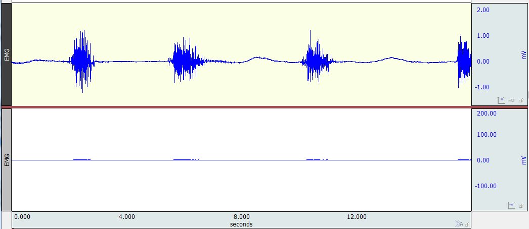
There are many possible reasons for a flat signal. It is important to make a distinction between the data (the numbers that the computer is actually recording) and the display of the data (how the numbers are shown in the graph window). The two channels shown in the image below contain the exact same data; the lower channel is a duplicate of the upper. However, the lower channel is displayed with a much coarser scale (zoomed out).

The first troubleshooting step is to re-scale the display of the data. There are multiple ways to do this, but one is to select the channel and click the vertical autoscale button in the toolbar.
If scaling is not the issue, the next step is to ensure that channel setup is correct.
- Is the channel selector switch (for most modules this is on the top of the amplifier) in the position corresponding to the number of the channel that is displaying a flat line in the software? If not, then move the switch or tell the software what the correct channel is (see the video tutorial on how to set up data channels in AcqKnowledge for help).
- If the software and hardware agree on which channel is being used, are any other modules also set to communicate through that same channel?
- Are there any connections to the front of the interface module (AMI100D, HLT100D, or UIM100C), specifically into the Analog Channel corresponding to the one that is exhibiting a flat line?
- Please note that channel contention—more than one device attempting to use the same channel for communication—is a hardware issue. If there are two amplifiers connected to the same channel, results will be unpredictable. It does not matter whether the software was configured to use only one of the two devices. That the software does not “know” there is a channel contention issue does not make that issue go away. You can learn more about Channel Contention here.
If neither channel scaling nor channel setup is the cause of the flatline, verify that all equipment is securely connected.
Also make sure that all relevant switches are in the “On” position.
If the system has not been used before, make certain that a signal is expected under the present conditions.
- For instance, if recording a biopotential signal (EEG, ECG, EDA, etc.) do electrodes have the appropriate gels? Are all necessary electrodes connected? If using shielded leads, are the proper connections being made (connecting the lead’s shields to the active contacts, VIn+ and VIn–, should produce a flat line at zero volts)?
If answers to all of those questions are “yes”, only then is it time to entertain the possibility of a hardware failure.
- If the signal is a biopotential signal, the electrodes and leads should be verified. Pre-gelled electrodes will dry out if not properly stored. If no gel bridges the electrode surface to the interstitial fluids in the subject’s skin, no signal is expected. The lead wires should also be tested for continuity. Most digital voltmeters have a setting that will allow the measurement of impedance. With one of the probes of the voltmeter touching the metal surface that contacts the button snap on the electrode and the other making contact with the metal part of the connector to the amplifier (with a touchproof connector, you may need to use a paper clip or some other item to insert into the connector to reach the metal if the voltmeter’s probe is too large to be inserted), the resistance should be one ohm or less for most leads (radio translucent leads for MRI research will have somewhat higher resistance).
Stay Connected